1. SCOPE
1.1 This Standard Practice covers essential dimensions,finish,tolerances,testing,marking,material and minimum strength requirements for 90 and 45 degree integrally reinforced forged branch outlet fittings of buttwelding,socket welding and threaded types.
1.2 Fittings manufactured to this Standard Practice are designed to make a fully reinforced branch connection in accordance with applicable piping code requirements,when attached,at an opening in a run pipe by means of a full penetration weld.
1.3 Fittings may be made to special dimensions,size,shape,tolerances or of other wrought material by agreement between the manufacturer and the purchaser.
1.4 Standard Units Tables 2 through 7 show the fitting’s dimensional requirements in customary units or inches (decimal).Tables A2 through A7 show the fitting’s dimensional requirements in SI (metric) units (e.g., millimeters). The values stated in either customary or SI (metric) units are to be regarded separately as the Standard.Within the body text,the SI (metric) units are shown in parenthesis.Combining values from the two systems may result in non-conformance with the Standard Practice.The values stated in each option are not exact equivalents;therefore,each measurement system must be used independently of the other.
2.SERVICE DESIGNATION
2.1 These fittings are designated by their size,type and class,as shown in Table 1. 2.2 Design temperature and other service conditions shall be limited as provided by the applicable piping code or regulation for the material of construction of the fitting.Within these limits, the maximum allowable pressure of a fitting shall be that computed for straight seamless run pipe of equivalent material (as shown by comparison of composition and mechanical properties in the respective material specifications).The wall thickness used in such computation shall be that tabulated in ASME B36.10M for the size and applicable schedule of pipe reduced by applicable manufacturing tolerances and other allowances (e.g., threaded allowances).
2.3 Any corrosion allowance and any variation in allowable stress due to temperature or other design factors shall be applied to the pipe and fitting alike.The pipe wall thickness corresponding to each Class of fitting,for rating purposes only,is shown in Table 1.
TABLE 1: Correlation of Fittings Class with Schedule Number or
Wall Designation of Run Pipe for Calculation of Ratings
|
Class of Fitting
|
Type
|
Branch Size
|
Pipe Wall for Rating Basis
|
|
Standard
|
Buttwelding
|
NPS 1/8 – 24
|
Standard
|
|
Extra Strong
|
Buttwelding
|
NPS 1/8 – 24
|
Extra Strong
|
|
Schedule 160
|
Buttwelding
|
NPS 1/2 – 6
|
Schedule 160
|
|
3000
|
Threaded & Socket Welding
|
NPS 1/8 – 4
|
Extra Strong
|
|
6000
|
Threaded & Socket Welding
|
NPS 1/2 – 2
|
Schedule 160
|
3. SIZE
3.1 The 90 and 45 degree branch outlet sizes considered in this Standard Practice are shown in Table 1.Size on size fittings shall be limited to outlet sizes NPS 1/2 (DN 15) and larger.
3.2 The run (header) pipe size is limited only by the pipe size range listed for each type fitting class.
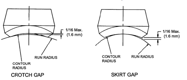
3.3 The manufacturer has the option to consolidate run sizes for a given branch size for economic reasons,provided the designated consolidation gap distance between the run pipe radius and the fitting inlet radius does not exceed 1/16″ (1.6 mm). See Figure 1. 4. MARKING
4.1 Each fitting shall be permanently marked with the required identification by raised lettering,and/or by stamping, electro-etching or vibro tool.
4.2 The marking shall include (but it is not limited to) the following:
Manufacturer’s name or trademark.
b) Material Identification The material shall be identified in accordance with the marking requirements of the applicable ASTM Specifications,including Heat Identification.
c) Class The Fitting Class-“STD” (Standard), “XS” (Extra Strong), “SCH 160” (Schedule 160), “3000” or “6000”. Alternatively, the designation 3M or 6M,as applicable,may be used where “M” stands for 1,000.
d) Size The nominal size of the pipe that the fitting’s marking identifies Run (or consolidated range) NPS (DN) x Outlet NPS (DN). e) SP 97 This marking indicates compliance with MSS SP-97.
4.3 Where size and shape of fittings do not permit all of the above markings,they may be omitted in the reverse order given above.
5. MATERIAL
5.1 The material for fittings, under this Standard Practice,shall consist of forging,bar,and seamless tubular products. The materials shall conform to the requirements of the WP Grade seamless construction materials in ASTM Fitting Specifications A234/A234M, A403/A403M,A420/A420M,or A815/A815M;or the ASTM Forging Specifications A105/A105M,A182/A182M,or A350/A350M.
5.2 All other forging,bar,and seamless tubular products listed in ASME B16.34 Table 1;including the applicable “notes” of ASME B16.34 Table 1,Table 2,or Appendix VII tables,may be used.
6. DESIGN AND DIMENSION
6.1 A run pipe having a branch connection is weakened by the opening made in it.The branch connection must reinforce the opening and restore the original strength of the run pipe.It is the intent of this Standard Practice that these integrally reinforced branch outlet fittings and the deposited weld metal used to attach the fittings to run pipes contain all the reinforcement required by the applicable pressure vessel or piping codes without the addition of saddles or pads.
6.1.1 The adequacy of the design of branch connection fittings may be established by mathematical analyses contained in pressure vessel or piping codes,or,at the manufacturer’s option,by proof testing in accordance with Section 7 and Annex B. Records of design or proof tests shall be available at the manufacturer’s facil
ity for inspection by the purchaser.
6.1.2 The pressure vessel or piping codes referred to in Section 6.1.1 permit a variety of attachment welds for these fittings.Typical branch attachments are shown in ASME B31.1 and B31.3.
6.1.3 Fittings shall be contoured to provide a good fit at the opening in the run pipe.The run attachment weld bevel angle design will vary with the size and type of fitting and with the manufacturer.The size of the run opening is dependent on the manufacturer’s specification.
6.2 Buttwelding Buttwelding end finishes shall comply with the standard welding bevel and root face of ASME B16.25.
6.3 Threads Threads in threaded fittings shall comply with ASME B1.20.1 requirements for NPT.
6.3.1 The minimum wall thickness at the root of the thread at the hand tight plane shall be equal to or greater than the nominal wall of the pipe schedule for the appropriate fitting class,as shown in Table 1.6.4 Socket Weld Socket Weld fittings shall meet the minimum socket depth,minimum socket wall thickness and socket diameter of ASME B16.11 for the appropriate class. 6.5 The contour weld bevel angle on the longitudinal section of the fittings shall be a minimum of 35 degrees.The weld bevel angle on the transverse section of the fitting is based on the manufacturer’s specification.
7. TESTS
7.1 Hydrostatic testing of wrought fittings is not required by this Standard Practice.All fittings shall be capable of withstanding, without leakage or impairment of serviceability,a pressure equal to that prescribed in the applicable code or regulation for seamless pipe of equivalent material and schedule listed in Table 1.
7.2 Proof testing is not required,but when performed to meet the requirements of Section 6.1.1,the testing shall be conducted in accordance with Annex B.
Types of Branch Connection Fittings


