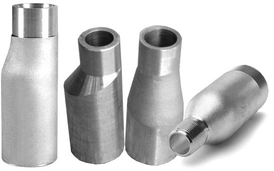
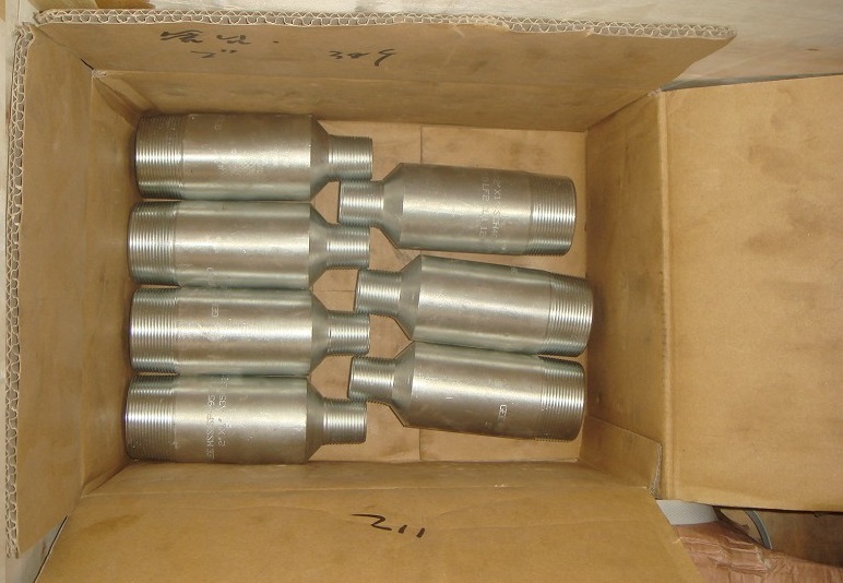
1.1 This standard covers dimensions, finish, tolerances, marking and material for carbon steel and alloy steel Swaged Nipples (male end reducing fittings), NPS 1/4 through NPS 12 and Bull Plugs (hollow or solid male closures) NPS 1/8 through NPS 12. These fittings are made with ends that are threaded, beveled, square cut, grooved, or any combination of these. Both concentric and eccentric swaged nipples are included.
1.2 Partial Compliance Fittings
Fittings with special dimensions and fittings made from nonstandard materials may be designed and manufactured by agreement between the manufacturer and the purchaser, provided they are marked in accordance with the requirements for partial compliance fittings.
2.PRESSURE RATINGS
2.1 The allowable working pressure for fittings designed in accordance with this standard practire shall be calculated as for straight seamless pipe of equal end preparation in accordance with the rules established in the applicable sections of the American National Standard Code for Pressure Piping B31. The pipe wall thickness and type material shall be that for which the fittings have been ordered. Fittings shall be identified by pipe wall thickness and material grade in lieu of pressure rating.
2.2 The design of fittings may be established by mathematical analyses contained in nationally recognized pressure vessel or piping codes, or at the manufacturer’s option, by proof testing in accordance with Section 9. Records of design or successful proof tests shall be available at the manufacturer’s facility for inspection by the purchaser. Bull plugs shall meet the additional requirement that the minimum thickness of the head shall be at least 1.5 times the thickness of the corresponding pipe schedule. For bull plugs that are drilled and tapped, the minimum thickness of the head shall be increased to accommodate the minimum L2 thread length as specified in ANSI/ASME B1.20.1 – 1983 (reaffirmed 1992).
3.SIZE
3.1 Bull Plug size is identified by the “nominal pipe size” (NPS). Swaged Nipples are identified with the large end size listed first, followed by the small end size. (see Sec 4.1d)
4. MARKING
4.1 Each fitting shall have the prescribed information stamped or otherwise suitably marked in accordance with the following.
a) Manufacturer’s name or trademark
b) MaterialIdentification
Fittings shall be marked with the material grade in accordance with the applicable ASTM Fittings Specifications A 234, A 403, A 420 (e.g, WPB). The material lot or heat number traceable to the material shall be part of the material identification
c) Schedule number or nominal wall thicknessdesignation
d) Size: Nominal pipe size (NPS) of Bull Plug
Nominal pipe size (NPS}Large end X small end of Swaged) Nipples一Example: 2 X 1
e) Product Conformance
Full compliance fittings shall be marked with the symbol SP95 to denote conformance with this Standard. Partial compliance fittings covered in 1.2 shall not be marked “SP95” and if marked with an ASTM designation, the marking shall include the number of the applicable “Supplementary Requirement” for special or non-standard fittings.
4.2 Where size and shape of fittings do not permit all the above markings they may be omitted in the reverse order given above.
4.3 Minimum permanent marking is manufacturer’s name or trademark and material grade. At manufacturer’s option, all other marking may be permanent or applied on a pressure sensitive label.
4.4 Where steel stamps are used, care should be taken so that marking is not deep enough to reduce wall thickness of the fitting below minimum allowed.
5.MATERIAL
5.1 The steel for Swaged Nipples and Bull Plugs shall consist of forgings, round or hex bars or seamless pipe or tube which conform to the requirements of ASTM A 234, A 403, A 420 or the corresponding ASME Specification. When Swaged Nipples and Bull Plugs made of other materials reference this standard, they should be appropriately marked as agreed upon between manufacturer and purchaser.
6.DIMENSIONS
6.1 The dimensions of Swaged Nipples and Bull Plugs are shown in Tables 1, A1 and 2, A2 respectively. Tolerances are shown in Tables 3 and A3.
7.END PREPARATION
7.1 Pipe ends may be threaded, beveled for butt welding, square cut (plain) for socket welding, grooved, or any combination of these.
7.2 Threaded ends shall be in accordance with ASME B 1.20.1. Threads shall be chamfered at the ends of the fitting to protect the first thread. The reference point for gaging threads is the last thread scratch on the chamfer cone.
7.3 Butt-welding ends shall be in accordance with ASME B 16.25.
7.4 Grooved ends shall be by agreement between manufacturer and purchaser.
8.SURFACE OUALITY
8.1 Fittings supplied under this specification shall be in accord with surface quality requirements of ASTM A 234, A 403, A 420.
9.1 Proof tests shall be made as set forth herein, when the manufacturer chooses proof testing to qualify the fitting design.
9.2 Test Assembly
9.2.1 Fittings selected for test shall be representative of production and shall meet all the requirements of this standard practice and the applicable material specification. The fittings shall be inspected for dimensional compliance to this standard. Full material specification test reports, including chemical analysis, tensile and hardness property results shall be included in the records of the proof tests.
9.2.2 Straight seamless or welded pipe sections, whose calculated bursting strength is at least as great as the computed proof test pressure as calcufated in Para. 9.3 shall be welded to each end of the fitting to be tested. Any internal misalignment greater than 0.06 inch (1.6 mm) shall be reduced by taper boring at a slope not over 1:3. Length of pipe sections for closures shall be at least twice the pipe OD.
9.3 Test Procedure
9.3.1 The test fluid shall be water or other fluid used for hydrostatic testing.
9.3.2 Hydrostatic pressure shall be applied to the test assembly. The test is successful if the assembly withstands, without rupture 105% of the computed test pressure defined below:
P=2St/D
where:
P=computed test pressure, psig
S=minimum tensile strength of the test fitting
t=minimum wall thickness of the pipe that the fitting marking identifies, inches
D=specified outside diameter of the pipe, inches
9.3.3 As an alternative, if the pipe ruptures, or if sufficient pressure to rupture any part of the assembly cannot be attained, the test pressure is acceptable if a final test pressure is at least 105 percent of the computed proof test pressure.
9.4 Annlicability of Test Results It is not necessary to conduct an individual test of fittings with all combinations of sizes, wall thickness, end connections, and grade of steel. A successful proof test on one prototype fitting may represent others to the extent described herein.
9.4.1 One test fitting may be used to qualify similar ones no smaller than one-half nor 1arger than two times the size of the test fittings.
9.4.2 The untested fittings must have a t/D ratio not less than one-half nor more than three times the tlD ratio of the test fitting.
9.4.3 The pressure retaining capacity of a fitting made of various grades of steel will be essentially directly proportional to the tensile properties of the various grades. Hence, it is necessary to test a prototype in only a single grade to prove the geometric design of the fittings.
10.TESTING
10.1 Hydrostatic testing of fittings is not required in this standard. All fittings shall be cagable of withstanding without leakage a test pressure equal to that prescribed in the specification, for the pipe of equal end preparation, with which the fitting’s rnarkinQ identifies.

Swaged Concentric Nipple and Swaged Eccentric Nipple


