1.1 SCOPE
This Standard specifies requirements for circular flanges of nominal sizes DN 15 to DN 3000, inclusive, and their bolting for use on pipes, valves, fittings and other pressure-retaining equipment containing fluid at pressures up to 19 300 kPa and at temperatures in the range −200°C to +525°C.
These flanges are manufactured from carbon steel, carbon-manganese steel, alloy steel,stainless steel, grey iron, malleable iron, ductile cast iron*, or copper alloy.
This Standard is applicable to flanges for water, steam, compressed air, chemical and petroleum plants, hydraulic piping and where other Standards require compliance with this
Standard.This Standard is not intended to apply to flanges for water or waste water covered by AS 4087.
Flanges R, S and T are designated obsolescent and are not recommended for use in new equipment. They are retained to provide for the servicing of existing equipment that is expected to have a long working life. For new equipment, flanges R, S and T should be replaced with flanges to AS/NZS 4331, Parts 1 to 3, ANSI B16.5 or BS 4504 (series).
The history of AS 2129 flanges (and its predecessor BS 10) and the future use of these flanges is given in the Preface.
1.2 OBJECTIVE
The objective of this Standard is to provide guidance to pipe fittings manufacturers and users on the materials, manufacturing requirements and dimensions of circular flanges for use with existing or new equipment.
1.3 APPLICATION
1.3.1 Flanges
Flanges shall comply with the relevant requirements of this Section and with the specific requirements of the following Sections, as appropriate:
Section 2—Temperature/Pressure Ratings.
Section 3—Materials.
Section 4—Manufacturing Requirements and Dimensions.
Section 5—Marking and Material Certificates.
Section 6—Dimensions of Flanges.
1.3.2 Bolting
Bolting for flanges shall comply with the requirements of Appendix A.
1.3.3 Assembly
The assembly of flanged joints shall comply with the requirements of Appendix B.
1.4 REFERENCED DOCUMENTS
The documents referred to in this Standard are listed, with titles, in Appendix C.
1.5 DEFINITIONS
For the purposes of this Standard, the following definitions apply:
1.5.1 Flange contact surface—that part of the flange face upon which the gasket is compressed.
1.5.2 Flange face—the reference plane which is perpendicular to the axis of the flange and coincident with the front of the flange from which is measured the thickness of the flange and also the height of the raised face or the depth of the O-ring groove. The profile of the front of a flange may be flat face*, raised face, or flat face with O-ring. (See Figure 1.1.)
NOTE: For convenience, only the flat face variant of each type has been illustrated.
flange which is cast or forged as part of a pressure-containing component.
1.5.6 Nominal size (DN)—a numerical designation of size which is common to all components in a piping system other than components designated by outside diameters or by thread size. It is a convenient round number for reference purposes and is only loosely related to manufacturing dimensions.
1.5.7 Pressure—the gauge pressure of the fluid contained by the pressure-containing component.
1.5.8 Temperature—the temperature of the fluid contained by the pressure-containing component to which the flange is attached, unless otherwise stated.
1.6 CONFIGURATION
1.6.1 General Flange configuration is determined by—
(a) the type, as specified in Clause 1.6.2; and
(b) the face, as specified in Clause 1.6.3.
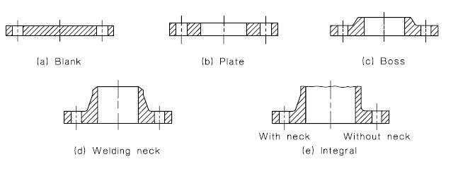
1.6.2 Type
The types of flanges are as illustrated in Figure 1.2.
1.6.3 Flange faces Each of the basic types may have, subject to the limitations given in Table 4.1, any one of the faces illustrated in Figure 1.1.
NOTE: For convenience, only the flat face variant of each type has been illustrated.
1.7 LIMITATIONS ON THE USE OF FLANGES
Limitation on the use of a flange may be imposed by any one or more of the following:
(a) Material.
(b) Flange table.
(c) Flange type.
(d) Fluid.
(e) Temperature.
(f) Hydrostatic test pressure.
The hydrostatic test pressure of a flange, when installed in a system, shall not exceed the maximum allowable hydrostatic test pressure (at nominal 20°C) shown in the appropriate Table (Tables 2.1 to 2.10).
Limitations of a particular nature may be imposed for specific applications by the relevant application Standard which should be consulted. Flange Tables A, D and E may not be suitable for use with hard gaskets, such as spiral wound gaskets, or narrow face gaskets, as the flange may deform permanently before satisfactory seating loads are achieved. (Refer also to Paragraph B3.2 for gasket selection.)
NOTE: For convenience, only the flat face variant of each type has been illustrated.
1.8 NON-STANDARD THICKNESS FLANGES
The thickness of a flange may be reduced by up to 5% from the tabulated thickness provided—
(a) the yield strength of the flange material is at least 20% stronger than the minimum
specified yield strength of a material listed for the particular flange;
(b) the purchaser agrees; and
(c) the flange is designated as non-standard.
1.9 NOMINAL SIZE AND OUTSIDE DIAMETER
Appendix D tabulates, for the nominal size (DN), the outside diameter of pipes in accordance with the relevant Standards.


