This Standard covers the preparation of butt welding ends of piping components to be joined into a piping system by welding. It includes requirements for welding bevels, for external and internal shaping of heavy-wall components, and for preparation of internal ends (including dimensions and tolerances).
Coverage includes preparation for joints with the following: no backing rings; split or noncontinuous backing rings; solid or continuous backing rings; consumable insert rings; gas tungsten arc welding (GTAW) of the root pass.
ANSI/ASME B16.25 Standard covers the preparation of butt welding ends of piping components to be joined into a piping system by welding. It includes requirements forwelding bevels, for external and internal shaping of heavy-wall components, and for preparation of internal ends (including dimensions and tolerances).
Coverage includes preparation for joints with the following:
(a) no backing rings
(b) split or noncontinuous backing rings
(c) solid or continuous backing rings
(d) consumable insert rings
(e) gas tungsten arc welding (GTAW) of the root pass Details of preparation for any backing ring must be specified when ordering the component.
ANSI/ASME B16.25 Standard applies to any metallic materials for which a welding procedure can be satisfactorily qualified, but does not prescribe specific welding processes or procedures. Unless otherwise specified by the purchaser, it does not apply towelding ends conforming to ASME B16.5, ASME B16.9, or ASME B16.47. Send us your technical drawings: Haihai Group will supply you with whatever flanges you are looking for.
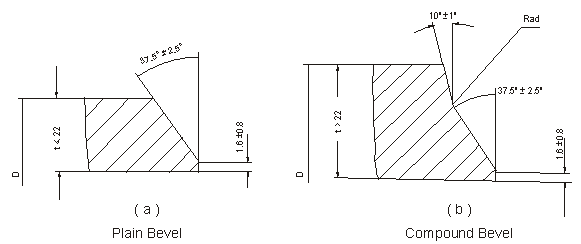
| Nominal wall Thickness : t | End Preparation |
| t<5mm (for austenitic alloy steel t<4mm) | Cut square or slightly chamfer at manufacturer ‘ s option |
| 5<t<22mm (4<t<22mm) | Plain Bevel as in sketch ( a ) above |
| t>22mm | Compound Bevel as in sketch ( b ) above |
WELDBEND NOTES:
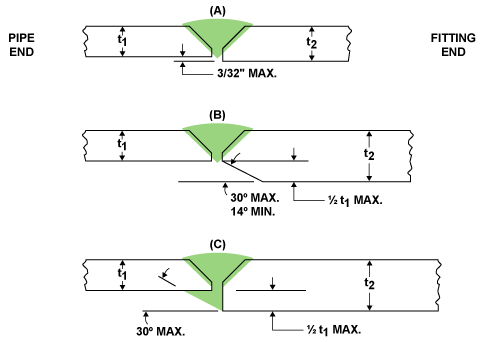
Weld neck flanges can be joined to pipe of lesser wall with proper end preparation and joint design. The recommendations that follow apply to weld neck flanges with standard plain end bevels (as shown above) and with a hub thickness at the bevel no greater than 1 1/2 times the mating pipe thickness.
The thickness of the flange hub at the weld bevel and the pipe shall be in accordance with the design requirements of the applicable section of ASME B31 Code for Pressure Piping. When the internal offset due to unequal thickness does not exceed 1/2 times the pipe wall thickness, then the rules and figures given on page 75 are recommended as well for joining weld neck flanges to pipe of lesser wall and/or higher strength.
When the additional thickness of the hub at the bevel results in an offset at the outside diameters of the ends to be joined, reference should be made to ASME B31 and ASME B16.5 Bevel Wall Thickness (t) 0.19 In. To 0.88 In. Inclusive A = Outside Diameter of flange and mating pipe (inches) B = Inside Diameter of flange (inches) t = Wall thickness of flange hub at bevel (inches) Note: For bevel wall thickness over .88″ refer to ASME B16.5 for alternative detail.


